No doubt you’ve heard people say that metalworking is “more of an art than a science.” If you’ve ever watched the learned hands of a bonafide craftsman piece together a stunning custom bike or a breathtaking bomber seat for a hot rod using only tools that he made and knowledge born only from the gallons of sweat spilled on his dirty shop floor, you know metal fabrication is an art. But beneath those dirty fingernails and stained welding gloves, there’s a lot of science at work.
We’re about to get technical—like really technical. Every so often, we have to break out our book learning. And while we’d rather be bending a cage back in our shop right now, too, but we think you’d like to know just what’s going on when you throw a stick of material into your tube bender and wrap it around the die. So without further ado, we bring you: wall factor and “D” of bend. To those of you who didn’t just click your browser’s back button, here we go:
The Goal of Tube Bending
Whether you’re bending up mild steel for a roll cage or some wild alloy for aerospace parts, the goal of tube bending stays constant: produce smooth, round bends. Here’s where it gets tricky. “When the tube or pipe is bent, fibers at the outside wall are in tension and fibers at the wall on the inside bend are in compression. This condition of tensile stress causes thinning and elongation of the wall at the outside, and the compression stress causes thickening and shortening of the inner wall. As a result, the cross-section of the bent section of the tube is flattened.” (Machinery’s Handbook 1382) Translation: the tube takes on a slightly oval shape (and that’s okay!). The question is how to minimize that effect.
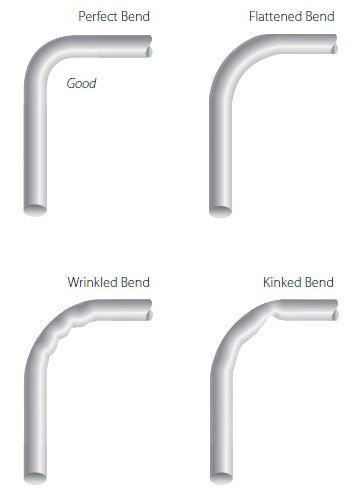
(Photo Credit: Aviation Online Magazine)
To create a quality bend, many factors are at play: type (and, by extension, quality) of your material, outside diameter, wall thickness, and centerline radius. (If you're still confused on those terms, check out our Tube and Pipe Bending Basics page.) The relationship between those parameters determine whether or not you can perform a bend and if you need a mandrel to do so. Hence, our bending die charts include minimum wall thickness specs for OD and centerline radius.
Wall Factor
The first relationship to evaluate is wall factor: the ratio between the outside diameter of the material and its wall thickness.
The lower the wall factor, the easier a bend is to make. If the wall factor is too high, the bend might require a series of dies to make it work and may even be impossible. Here’s a chart for a common range of sizes:
|
Wall Factor |
||||||||||
|
|
Wall Thickness |
|||||||||
|
0.035" |
0.049" |
0.058" |
0.065" |
0.083" |
0.095" |
0.109" |
0.120" |
0.134" |
||
|
Outside Diameter |
0.500" |
14.3 |
10.2 |
8.6 |
7.7 |
6.0 |
5.3 |
4.6 |
4.2 |
3.7 |
|
0.625" |
17.9 |
12.8 |
10.8 |
9.6 |
7.5 |
6.6 |
5.7 |
5.2 |
4.7 |
|
|
0.750" |
21.4 |
15.3 |
12.9 |
11.5 |
9.0 |
7.9 |
6.9 |
6.3 |
5.6 |
|
|
0.875" |
25.0 |
17.9 |
15.1 |
13.5 |
10.5 |
9.2 |
8.0 |
7.3 |
6.5 |
|
|
1.000" |
28.6 |
20.4 |
17.2 |
15.4 |
12.0 |
10.5 |
9.2 |
8.3 |
7.5 |
|
|
1.125" |
32.1 |
23.0 |
19.4 |
17.3 |
13.6 |
11.8 |
10.3 |
9.4 |
8.4 |
|
|
1.250" |
35.7 |
25.5 |
21.6 |
19.2 |
15.1 |
13.2 |
11.5 |
10.4 |
9.3 |
|
|
1.375" |
39.3 |
28.1 |
23.7 |
21.2 |
16.6 |
14.5 |
12.6 |
11.5 |
10.3 |
|
|
1.500" |
42.9 |
30.6 |
25.9 |
23.1 |
18.1 |
15.8 |
13.8 |
12.5 |
11.2 |
|
|
1.625" |
46.4 |
33.2 |
28.0 |
25.0 |
19.6 |
17.1 |
14.9 |
13.5 |
12.1 |
|
|
1.750" |
50.0 |
35.7 |
30.2 |
26.9 |
21.1 |
18.4 |
16.1 |
14.6 |
13.1 |
|
|
1.875" |
53.6 |
38.3 |
32.3 |
28.8 |
22.6 |
19.7 |
17.2 |
15.6 |
14.0 |
|
|
2.000" |
57.1 |
40.8 |
34.5 |
30.8 |
24.1 |
21.1 |
18.3 |
16.7 |
14.9 |
|
|
2.125" |
60.7 |
43.4 |
36.6 |
32.7 |
25.6 |
22.4 |
19.5 |
17.7 |
15.9 |
|
|
2.250" |
64.3 |
45.9 |
38.8 |
34.6 |
27.1 |
23.7 |
20.6 |
18.8 |
16.8 |
|
|
2.375" |
67.9 |
48.5 |
40.9 |
36.5 |
28.6 |
25.0 |
21.8 |
19.8 |
17.7 |
|
|
2.500" |
71.4 |
51.0 |
43.1 |
38.5 |
30.1 |
26.3 |
22.9 |
20.8 |
18.7 |
|
"D" of Bend
The second relationship to evaluate is “D” of bend (yes, that is the technical name). This is the ratio between the centerline radius of the bend and the outside diameter of the material.
The rules for this relationship are opposite of those for wall factor. When it comes to “D” of bend, you’re looking for a larger number. The larger the number, the easier it is to form the bend. Here’s a small chart like the last one:
|
"D" of Bend |
||||||||||
|
|
Centerline Radius |
|||||||||
|
2.000 |
2.500 |
3.000 |
3.500 |
4.000 |
4.500 |
5.000 |
6.000 |
7.000 |
||
|
Outside Diameter |
0.125 |
16.0 |
20.0 |
24.0 |
28.0 |
32.0 |
36.0 |
40.0 |
48.0 |
56.0 |
|
0.250 |
8.0 |
10.0 |
12.0 |
14.0 |
16.0 |
18.0 |
20.0 |
24.0 |
28.0 |
|
|
0.375 |
5.3 |
6.7 |
8.0 |
9.3 |
10.7 |
12.0 |
13.3 |
16.0 |
18.7 |
|
|
0.500 |
4.0 |
5.0 |
6.0 |
7.0 |
8.0 |
9.0 |
10.0 |
12.0 |
14.0 |
|
|
0.625 |
3.2 |
4.0 |
4.8 |
5.6 |
6.4 |
7.2 |
8.0 |
9.6 |
11.2 |
|
|
0.750 |
2.7 |
3.3 |
4.0 |
4.7 |
5.3 |
6.0 |
6.7 |
8.0 |
9.3 |
|
|
0.875 |
2.3 |
2.9 |
3.4 |
4.0 |
4.6 |
5.1 |
5.7 |
6.9 |
8.0 |
|
|
1.000 |
2.0 |
2.5 |
3.0 |
3.5 |
4.0 |
4.5 |
5.0 |
6.0 |
7.0 |
|
|
1.125 |
1.8 |
2.2 |
2.7 |
3.1 |
3.6 |
4.0 |
4.4 |
5.3 |
6.2 |
|
|
1.250 |
1.6 |
2.0 |
2.4 |
2.8 |
3.2 |
3.6 |
4.0 |
4.8 |
5.6 |
|
|
1.375 |
1.5 |
1.8 |
2.2 |
2.5 |
2.9 |
3.3 |
3.6 |
4.4 |
5.1 |
|
|
1.500 |
1.3 |
1.7 |
2.0 |
2.3 |
2.7 |
3.0 |
3.3 |
4.0 |
4.7 |
|
|
1.625 |
1.2 |
1.5 |
1.8 |
2.2 |
2.5 |
2.8 |
3.1 |
3.7 |
4.3 |
|
|
1.750 |
1.1 |
1.4 |
1.7 |
2.0 |
2.3 |
2.6 |
2.9 |
3.4 |
4.0 |
|
|
1.875 |
1.1 |
1.3 |
1.6 |
1.9 |
2.1 |
2.4 |
2.7 |
3.2 |
3.7 |
|
|
2.000 |
1.0 |
1.3 |
1.5 |
1.8 |
2.0 |
2.3 |
2.5 |
3.0 |
3.5 |
|
|
2.125 |
0.9 |
1.2 |
1.4 |
1.6 |
1.9 |
2.1 |
2.4 |
2.8 |
3.3 |
|
|
2.250 |
0.9 |
1.1 |
1.3 |
1.6 |
1.8 |
2.0 |
2.2 |
2.7 |
3.1 |
|
|
2.375 |
0.8 |
1.1 |
1.3 |
1.5 |
1.7 |
1.9 |
2.1 |
2.5 |
2.9 |
|
|
2.500 |
0.8 |
1.0 |
1.2 |
1.4 |
1.6 |
1.8 |
2.0 |
2.4 |
2.8 |
|
Wall factor and “D” of bend are interrelated in evaluating the limits of tube bending. Here’s a very general (very rudimentary) rule of thumb for benders without an inside mandrel is: multiply the outside diameter of the material by three; that’s the minimum achievable centerline radius for given material. Machinery’s Handbook illustrates this crucial relationship in a much more sophisticated fashion:
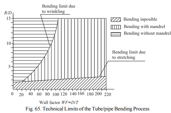
(Image Credit: Machinery’s Handbook 1383)
By plotting the wall factor and “D” of bend on a chart like this, you can determine if the part you want to bend is even possible (and how much it’s going to cost you to do so). Here’s the catch (c’mon—you knew it wouldn’t be that simple): those curves are material-specific. For different types and grades of materials, those curves change and what might be possible with one material might not be possible with another. If you need some help figuring all of this out, we don’t mind if you drop us a line. We’d be more than happy to help you out.
*Roll the Credits*
Oberg, Erik, Franklin D. Jones, Holbrook L. Horton, and Henry H. Ryffel. PIPE AND TUBE BENDING. Machinery's Handbook. Ed. Christopher J. McCauley. 29th ed. New York: Industrial Press, 2012. 1382-1386. Print.
Correct and Incorrect Tubing Bends. Digital image. Aviation Online Magazine. N.p., n.d. Web. 25 June 2015. <http://avstop.com/ac/Aviation_Maintenance_Technician_Handbook_General/7-3.html>.
T.C.V. Desaa
This is very excellent information for pipe fabricating work. Highly appreciate and thanks your post and these information is very useful all the people in the world who involve pipe fabrication work in order to minimize the overlity of pipe bending process. Further thanks.